Case
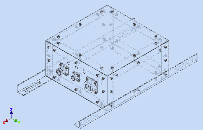
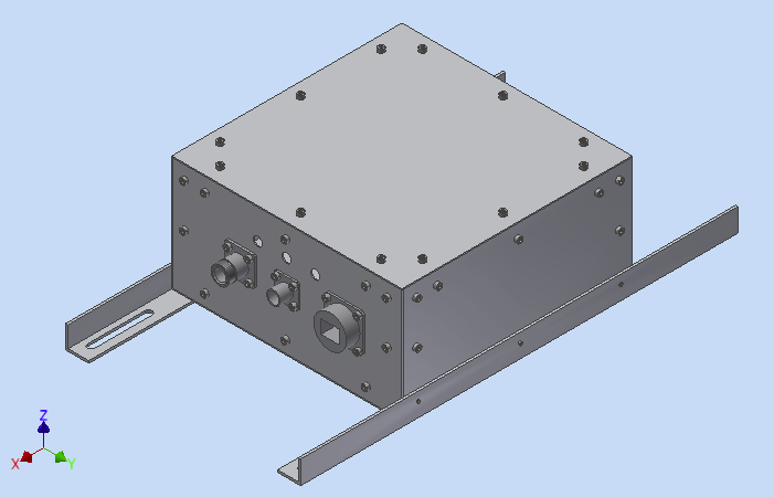
These are the CAD drawings to see how the experiment will look like. We try to keep the weight down as much as possible, while still maintaining good isolation from outside weather conditions, because it seems to get quite cold at 25km altitude.
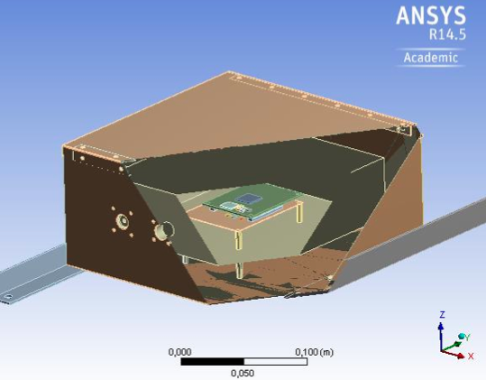
Simulation results seem good so far, with good thermal insulation we should be able to keep the sensitive electronics safe and warm.
Beside the connectors for power, e-link (ethernet) for communication and the n-connector for the antenna, there will be 3 LEDs to see, if different subsystems of the experiment are working correctly.
Antenna mounting
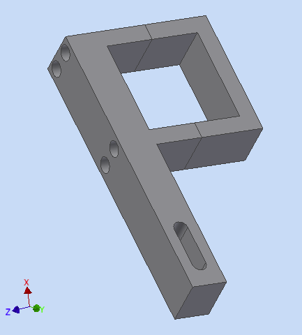
The antenna will be mounted with a bracket (see below) to one of the vertical bars of the BEXUS gondola. The antenna, in form of a rigid plastic tube is directly attached to the feeding coaxial cable. Not the antenna itself, but only the coaxial cable is passed through the hole, and withheld from slipping through by two cable ties. To keep the minimum bend radius, the cable is guided in a bend and attached to the bracket arm with another cable tie. From there on, the cable is strain relieved and can be routed to the N-connector on the front panel of the experiment.


